Airfield pavements and the A380
- Like
- Digg
- Del
- Tumblr
- VKontakte
- Buffer
- Love This
- Odnoklassniki
- Meneame
- Blogger
- Amazon
- Yahoo Mail
- Gmail
- AOL
- Newsvine
- HackerNews
- Evernote
- MySpace
- Mail.ru
- Viadeo
- Line
- Comments
- Yummly
- SMS
- Viber
- Telegram
- Subscribe
- Skype
- Facebook Messenger
- Kakao
- LiveJournal
- Yammer
- Edgar
- Fintel
- Mix
- Instapaper
- Copy Link
Posted: 6 June 2017 | Cyril Fabre | Head of Airfield Pavement Airport Operations | Airbus | 2 comments
Cyril Fabre, Head of Airfield Pavement – Airport Operations at Airbus, discusses the paradox of why the heaviest commercial airplane remains the most pavement-friendly aircraft at large hub airports?


Airfield pavement (runways, taxiways, aprons/stands) represents approximately 30% of initial airport infrastructure investments and between 30 and 40% of annual maintenance costs. Since the end of WWII, the global commercial aviation market has shown continuous air traffic growth, doubling every 15 years on average and demonstrating robust demand and resilience against external events. In parallel, airlines require aircraft to provide more range and seat capacity, which makes new generation aircraft heavier. To complicate matters further, airfield pavements are ageing and airport construction or expansion becomes more difficult – indeed, impossible in some areas. In this context, the actual condition of pavements must be continuously monitored, abnormal distress investigated and understood, in order to reduce maintenance costs and airline operation disruptions.
To complicate matters further, airfield pavements are ageing…
For the last two decades, the California Bearing Ratio (CBR) flexible pavement design procedure has been progressively replaced by the Multi-Layer-Linear-Elastic-Analysis (ML²EA) for pavement design and analysis. It will be adopted soon by the International Civil Aviation Organisation (ICAO) for pavement rating system, also known as the Aircraft/Pavement Classification Number or ACN/PCN method. Those methods rely on the linear elasticity theory, based on the Burmister’s mathematical model, supplemented recently by two major full-scale experimental programmes: the A380 Pavement Experimental Programme (A380 PEP) and the FAA National Airport Pavement Test Programme (NAPTP), which were used to develop a fully-calibrated methodology.
The new pavement design method allows some of the limitations and inconsistencies of the CBR procedure to be overcome and provides a much better picture of the operational impact on pavement when a traffic mix is applied on an airport pavement.
When comparing the CBR design procedure to the ML²EA for any project of pavement design, we recognise that the CBR design procedure systematically over-estimates pavement thickness for a given traffic mix reference and design pavement life. Applying the ML2EA remedies provides airports building a new pavement a way to make substantial cost savings.
If the A380 is a solution that addresses airport congestion, how does it also contribute to pavement damage in a traffic mix? The following explains why the aircraft does well, not only compared to other aircraft in terms of individual pavement loading, but also with its own contribution to the overall pavement cumulative damage being substantially lower than other aircraft composing the traffic mix.
Basics of the Multi-Layers-Linear-Elastic-Analysis (ML²EA)
From a high-level perspective, the rational approach involves the following two main steps:
- Determining stresses and strains in the pavement structure based on the Multi-Layer Linear Elastic Analysis (ML²EA), also known as ‘Burmister model’ (Burmister, 1944)
- Computing the pavement damage induced by the stresses and strains using a specific damage model. A damage model relies on one or several damage criteria with their associated damage law, the inputs of which are generally derived from laboratory tests.
Failure criterion and elementary damage law
Two damage criteria are usually considered in flexible pavement design, corresponding to different failure modes:
- Fatigue (resulting in gradual cracking) of bituminous layers (characterised by the maximum horizontal strain at the bottom of the asphalt surface layer εt)
- Permanent deformation of the subgrade (characterised by the maximum vertical strain at the top of the subgrade εz).
The former of these criteria is linked to the surface layers which may be subject to maintenance, while the latter is linked to the failure of the subgrade soil, hence to the structural pavement life. In pavement design and analysis, we consider only the subgrade failure mode, but good engineering practice would also require verifying the other criteria.
If the A380 is a solution that addresses airport congestion, how does it also contribute to pavement damage in a traffic mix?
By noting emax – the maximum amplitude of strain on top of subgrade – Wöhler’s law relates to the number of cycles C(emax) resulting in subgrade failure and can be wrote in the following form:


K and b are considered to be independent of the type of material and its water content, of the temperature and the speed of loading.
For high numbers of aircraft loading, the Wöhler’s law is associated with the Miner’s rule (also called, Damage additivity’s law). The Wöhler-Miner law is based on the notion of elementary damage, which postulates that the cumulative damage effect associated with the failure criterion equals 1 when failure (subgrade) occurs.
For one aircraft loading pass, this elementary damage is:


If the loading consists of several aircraft of varying amplitudes (traffic mix), the Wohler-Miner law stipulates:


Where:
Ci is the number of aircraft loading producing a maximum strain emaxi and,
D the cumulative damage produced after Ci passes of i aircraft.
The cumulative damage factor (CDF) is the amount of the structural fatigue life of a pavement that has been used up. It is expressed as the ratio of applied load repetitions to allowable load repetitions to failure, or, for one airplane and constant annual departures:


When CDF = 1, the pavement subgrade will have used up all of its fatigue life,
When CDF < 1, the pavement subgrade will have some remaining potential life and the value of CDF will give the fraction of the life used,
When CDF > 1, all of the fatigue life will have been used up and the pavement subgrade will have failed.
Multi-axles loading effect treatment
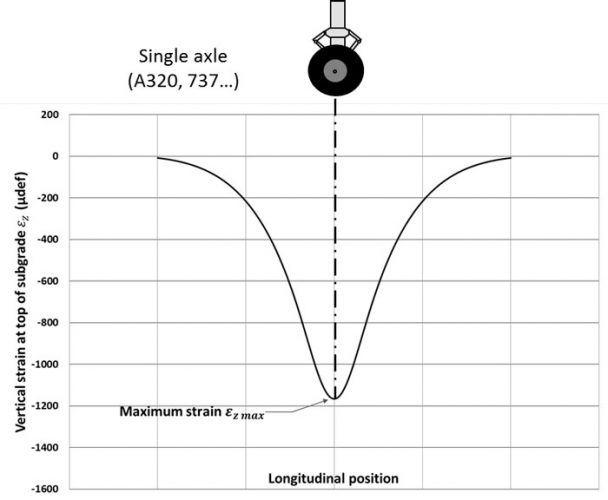
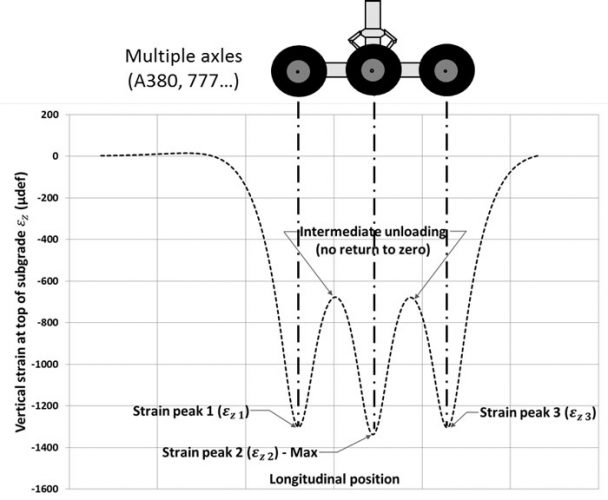
The above elementary damage laws are based on the notion of loading cycle. However, modern landing gears often feature multi-axles wheel groups (i.e. with wheels in tandem) that produce complex strain profiles in the pavement, possibly with multiple strain peaks and no return to zero between peaks. This is exemplified in Figure 1.


Figure 1
While elementary damage and CDF can apply to simple aircraft loading (dual wheel A320, 737 family), multi-axle loading aircraft (A380, 777, A350 etc.) consider the entire strain profile when computing the pavement damage. This approach accounts not only for the different peak strain values, but also the intermediate unloading between peaks.
For this purpose, the elementary damage law is extended to a continuous integral law thanks to the Miner’s rule. The damage D for a single aircraft pass is expressed in Equation 5.


Substituting Equation 2 in Equation 5, the latter becomes:


Where ε (x,y,zk) is the longitudinal profile of the variable ε, computed along the straight line (y,zk) and <F> the positive part of the equation F.
For the specific case of a single-peak strain profile with maximum amplitude εmax, Equation 5 reduces to the elementary damage law D = De (εmax).
A380 within a traffic mix
Based on these principles, we can easily evaluate how the A380 contributes to the maximum damage on a pavement when it is mixed with existing traffic.
Each aircraft composing the mix is assigned a number of annual departures over the pavement design life. For all aircraft composing the mix, the damage fatigue curve is then drawn along the runway cross section from the centreline to runway edge (note, for runways, a lateral wandering of ±.75m from the centreline is applied to each aircraft in the mix). The sum of each damage curve provides the overall damage curve of the complete mix and the location of the max CDF. It is then possible to determine the contribution of each aircraft composing the mix to the max CDF produced by the complete fleet.
Contrary to the CBR design procedure, the ML²EA method takes into account the real aircraft MLG general arrangement, in particular MLG overall track, which differs from one aircraft to another.
The A380 MLG overall track falls outside that of other long-range aircraft tracks. This is due to the airplane’s larger wingspan and lateral self-equilibrium requirement, among other design parameters. As a result, the A380 contribution to the max CDF is not located on the max A380 CDF, unlike other long-range aircraft whose max individual CDF falls closer to the location of the max CDF of the entire fleet.
The effect of this singular A380 MLG geometrical characteristic is independent of any pavement characteristics, whether it be pavement thickness, material or subgrade strength.
The below example illustrates this A380 feature, which may not be entirely obvious when considering its significantly higher maximum take-off weight compared to all other commercial aircraft.
For this purpose, we consider a pavement section (Table 1) with a design life of 10 years and a mix traffic (Table 2), each aircraft being assigned the same number of annual departures (10 movements/day) for the sake of a fair comparison.
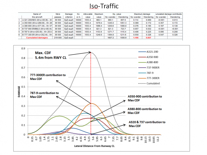
Table 3 details the maximum individual damage of each aircraft, the maximum damage resulting from the complete mix, and the contribution of each aircraft composing the mix to the maximum CDF. The resulting curves are shown in Figure 2.


Figure 2
Analysis
Figure 2 and Table 3 have to be analysed in light of aircraft MLG positioning in relation to the runway centreline. Indeed, an aircraft producing significant damage is not necessarily the most demanding aircraft; its damaging effect must be seen in relation to the cumulative damage produced by the complete fleet and the location of the max damage.
In this example, the A380 has the highest Maximum Ramp Weight (MRW), almost the weight of the 777-300ER and 787-9 combined, but its individual max damage effect is lower than both aircraft. This is due to its landing gear parameters, i.e. aircraft loads distributed over 20 wheels, gear geometry, and gear spacing designed for minimising wheel load interactions in the deeper layers (subbase and subgrade).
The A380 contribution to the max CDF is 30% less than its max CDF, and lower than other long-range aircraft, whilst the latter show a contribution to the max CDF equal to or close to their max individual CDF. The difference is a direct result of the aircraft MLG overall track characteristics. Indeed the A380 MLG track (distance from the Wing-Landing-Gear axle to Wing Landing-Gear axle) is about 12.5m wide, the other being narrower (between 10.6m and 11.9m).
Considerations and conclusion
Using the linear elastic technics allows many pavement analyses that the CBR design procedure would not permit.
The primary benefit to the airport owner is lower costs and improved pavement management with optimal use of their pavement infrastructures and proper management of aircraft operating weights and frequencies.
Nowadays, new airport construction projects are few and far between.
For instance, landing fees, which have to be paid by airlines for each landing, can vary greatly between airports, but their determination is always a function of many factors among which aircraft maximum weight remains the primary parameter, among others (including seat number, schedule of operation, etc.). These charges are then provisioned and used for airport infrastructure maintenance (or expansion). This logic is obviously unfair for the A380 since its effect on airport pavement infrastructure and its frequencies are lower than for most of the new aircraft generation. This is not intuitive, but it is reality. A fair system would determine landing fees on the basis of the CDF concept in place of the aircraft maximum weight. Such perspectives could be easily applicable at airports, provided they know precisely their pavement characteristics.
Nowadays, new airport construction projects are few and far between. Airport development and expansion are constrained. Continuous traffic growth at large hub airports makes the question of bigger and heavier large aircraft operations more pertinent than ever – and for decades to come. In the case of the A380, the impact on airfield pavements of additional operations at airports that are already been served, will fare between modest and non-existent. For airports that have yet to be served, the A380 requires no pavement reinforcement or rehabilitation since the additional movements have a minor impact on the max CDF produced by the existing traffic mix.
Cyril Fabre is Head of Airfield Pavement in the Airport Operations division of Airbus. He began working at Airbus in 1997 and joined the A380 programme (Formerly called Large Aircraft division) in the Infrastructure and Environment Department in 1999. He was appointed Head of A380 Pavement Experimental Programme (A380 P.E.P) and in March 2006 was appointed Airfield Pavement Manager for all Airbus products. Cyril was appointed Head of Airfield Pavement in the Engineering Aircraft Architecture & Integration Team in May 2007 and initiated and performed the High Tire Pressure test (HTPT) which served, with the FAA findings, the new ICAO tyre pressure limits code endorsed by ICAO in 2012 with applicability by ICAO State members since November 2013. He is currently developing the new ICAO pavement rating system (ACN/PCN method) on behalf of ICAO and manages the ground facility suitability for demonstrating the military capacities of the A400M on unpaved runways.


I have also analysed in 2008 in Dubai and found A380 is not as damaging to pavements as B777.
Very good analysis. But what is the effect of A380 on rubber deposit along the runway.