New loading modules for the pavement test vehicle
- Like
- Digg
- Del
- Tumblr
- VKontakte
- Buffer
- Love This
- Odnoklassniki
- Meneame
- Blogger
- Amazon
- Yahoo Mail
- Gmail
- AOL
- Newsvine
- HackerNews
- Evernote
- MySpace
- Mail.ru
- Viadeo
- Line
- Comments
- Yummly
- SMS
- Viber
- Telegram
- Subscribe
- Skype
- Facebook Messenger
- Kakao
- LiveJournal
- Yammer
- Edgar
- Fintel
- Mix
- Instapaper
- Copy Link
Posted: 28 March 2008 | Donald Barbagallo, Project Manager, FAA | No comments yet
From its dedication in 1999, the National Airport Pavement Test Facility (NAPTF), of the U.S. Federal Aviation Administration (FAA), has been tasked with conducting research on both rigid and flexible airport pavements. The facility offers a unique opportunity to study, instrument and record full-depth soil and pavement interactions under a variety of test parameters.
From its dedication in 1999, the National Airport Pavement Test Facility (NAPTF), of the U.S. Federal Aviation Administration (FAA), has been tasked with conducting research on both rigid and flexible airport pavements. The facility offers a unique opportunity to study, instrument and record full-depth soil and pavement interactions under a variety of test parameters.
Pavement experiments can be performed over three different subgrade soil strengths as measured by California Bearing Ratio (CBR): Low Strength (CBR 3-4), Medium Strength (CBR 7-8), and High Strength (CBR 25-30). Of particular interest to NAPTF engineers, are the load interactions which occur from multiple-wheel landing gear on a given pavement structure. To date, research conducted at the NAPTF has been instrumental in developing refined design procedures that provide more reliable predictions of pavement life from aircraft traffic.
The pavement test vehicle, with its ability to apply actual landing gear wheel loads to the test pavements, is the focal point of the facility. The capabilities of the test vehicle will soon be expanded, with the addition of four new load modules, to supplement the existing six load modules already on the vehicle.
Currently, the test vehicle can simulate the loads applied to a test section of airport pavement for a maximum of three dual-wheel modules, on each of its two movable carriages. This arrangement is adequate to emulate almost all present commercial airline landing gear wheel loads and configurations. However, airport pavement designers must currently rely on extrapolated data to evaluate eight and ten in-line wheel configurations. With the addition of the new load modules, the ten in-line landing gear wheel configuration of freighter aircraft, manufactured by Antonov ASTC, can now be simulated. Once pavement tests conducted with the new modules are completed, airport pavement designers will be able to use research-based data to replace the extrapolated data. Data derived from testing using the new loading modules, will also give commercial aircraft designers the ability to perform landing gear configuration studies for future aircraft, with more confidence than previously possible.
Test vehicle and load modules
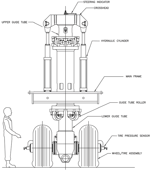
A load module consists of the tyres, axles, bearings, guide tubes, hydraulics and electronics that allow it to function as an equivalent aircraft landing gear (See Figure 1 on page 19).
As originally designed by Technodyne International Ltd and the Cornell Company, under a Cornell/DMJM design/build joint venture, each load module is self-contained, having the ability to be physically relocated along the structural carriage of the test vehicle. On the test vehicle, each load module has the primary responsibility of applying and maintaining a specified tyre wheel load during pavement testing; secondary systems measure tyre pressure and tyre temperature. Each load module features a servo-controlled, hydraulically-driven guide tube that can place up to 75,000lbs of load on each of the two tyres of the module.
There are two mobile structural carriages on the test vehicle. The carriages provide the reactive force to the load, that is placed upon a test section of pavement by the load modules and ultimately transfer that force to the rest of the test vehicle. Using a servo motor and gearbox, together with a rack and pinion, the carriages move along a transverse rail system mounted to the vehicle frame. The transverse spacing of the load modules is controlled by the movement of the carriages, giving the test vehicle the ability to replicate the transverse spacing of an actual landing gear configuration. During full scale pavement tests, the carriages are programmed to shift their relative positions laterally, in a wander pattern that simulates the observed deviation from dead centre of pavement load zones during normal aircraft operations.
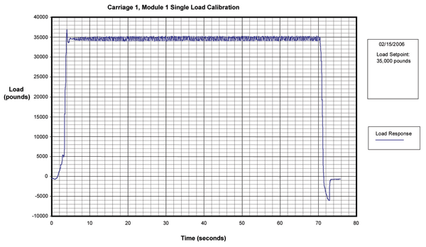
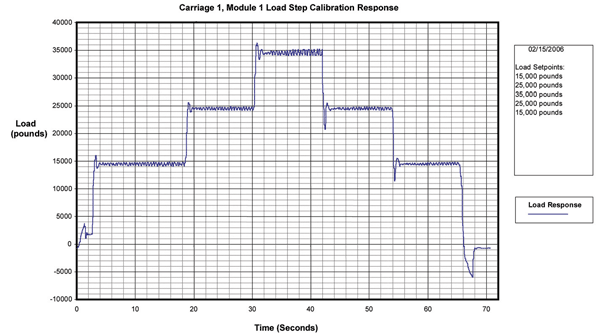
As test pavements begin to deform under the repeated loading from the modules, the ability of the load modules to make the physical adjustments necessary to maintain wheel contact, with precise loading, becomes crucial. The axles on each of the tandem wheels are free to individually pivot about the centre of the module, to allow each individual tyre to maintain contact with the pavement. The module’s vertical movement and load magnitude are controlled by an electronic-hydraulic feedback control system. A string potentiometer is used to track the load module’s vertical position, while pressure transducers supply the information necessary to calculate applied load. Each electronic-hydraulic control system consists of a Programmable Logic Controller (PLC), and an electronic module to control the high performance hydraulic servo valve. The hydraulic feedback loop of the control system calculates and adjusts the height and hydraulic load response of the load module, at a rate of one hundred times per second. To ensure accuracy, hydraulic loads applied by the control system are tuned and verified by calibrated heavyweight scales on a regular basis. The deviation between programmed loads to actual hydraulic pressure transducer recorded loads is typically +/- 2% during vehicle test operations. Figures 2 & 3 are plots of actual recorded module load responses for a single applied load and for a stepped applied load.
Similar to the existing load modules, the new load modules will be able to measure some of the physical properties of the aircraft tyres during pavement testing. This is necessary to maintain safe vehicle operation and to ensure that pavement testing parameters, such as loaded-tyre footprint, are held constant throughout the testing cycle. Tyre temperatures, measured by remotely mounted infra-red transducers, are monitored during pavement tests to ensure that excessively high tyre temperatures are not attained. Tyre inflation pressure, measured by a pressure transducer located on the bleed-off taken from a rotating coupling, is also monitored. Each of the above measurements can be set in the control system such that a variation of more than +/- 10%, from the nominal set value, will result in an alarm and/or vehicle shut-down. Tyre parameters are monitored at a frequency of one hertz.
Data collected by the PLCs, for both hydraulic loads and tyre conditions, is forwarded via fibre optics to the vehicle control cab for processing. The computers in the control cab of the test vehicle, together with the signal processing units gathering data from embedded pavement instruments, are linked via a wireless network to computers in the main building of the NAPTF, where the test data is reviewed and stored for each experiment.
New load module capabilities
While the new load modules will look very similar to the existing ones, there are a few new features that have been built into the new modules to help the NAPTF further its mission of airport pavement research. One of the goals at the NAPTF has been the study of “pavement shoving”, which results when transverse shearing forces are applied to the top layer of a Hot Mix Asphalt (HMA) pavement. These effects are often seen at the low speed turn areas of a runway. With the design help of FAA engineering support contractors at SRA International and Technodyne Intl LTD, design modifications were introduced into the upper bearing of the guide tube to permit +/- five degrees of steering of the new loading module. Future studies will take advantage of the shearing forces that result from the steered modules, to evaluate the shearing resistance of various HMA mixes.
Design changes to the tyres and rims have also been incorporated into the new load modules. Existing tyres on the test vehicle have always been bias ply with a 20-inch rim diameter. With the aircraft industry moving away from bias ply tyres, in favour of radial tyres on newer aircraft models, engineers at the NAPTF saw the opportunity to equip the new modules with larger radial tyres on 22-inch rims. These radial tyres will have a 10% greater load capacity than the existing bias ply tyres and will better emulate the footprint of the tyres on modern aircraft. Also, redesign of the tyre rim assembly will allow for easier tyre replacement; the rim assembly of the existing modules requires the removal of the wheel bearings in order to change a tyre. These refinements will allow the test module to move into the actual performance testing of aircraft tyres at some future date.
Module fabrication
A natural selection for manufacturing the new modules would have been the company originally involved with the module fabrication back in 1998. This was not to be, as that company’s business line had shifted out of manufacturing in favour of other endeavors. As a result, the moulds for the large castings, that form the crosshead and axle housing assembly of the load module, were no longer available. SRA International began a comparative search of machine shops capable of manufacturing and assembling the new modules. General Tool Company, of Cincinnati Ohio, had the proper mix of equipment and personnel necessary to accomplish the task; and fabrication work began in April of 2007 with the award of the construction contract. With the need to make new moulds contributing to an estimated delivery time of 18 to 20 weeks, the first task was to immediately order the new castings for the major parts. Working with an aggressive schedule, General Tool Company was able to obtain the required parts and complete all machining work by late autumn of 2007. Shop assembly of the modules began in December of 2007, with final shop testing and shipment of all four modules to the NAPTF scheduled for the spring of 2008.
Module installation and future test vehicle upgrades
Due to previously scheduled pavement test experiments at the NAPTF requiring extended use of the test vehicle, installation of the new load modules will occur in the autumn of 2008. Prior to the new module installation, the existing load modules, along with their hydraulic and electrical control systems, will be relocated to new positions on the vehicle carriages. The new modules, with their ability to be steered, will be installed directly opposing each other on each of the carriages. This is necessary to balance the torque generated by the steered wheels and to prevent an overall side force from being delivered to the top of the crane rail of the test vehicle.
It is currently planned to have the existing modules relocated as one complete assembly. After removing all electrical and hydraulic connections, the existing modules need only be lowered several inches into a support fixture. The test vehicle can then be moved longitudinally, until the existing module is raised and bolted into its relocated position. New modules will be shipped in two pieces to facilitate installation. Even in two pieces, it is anticipated that a five-foot deep trench will be required to provide the necessary undercarriage clearance for the new module installation. Work on new electrical and hydraulic connections to the modules can then begin. Provided that the module installation progresses according to plan, the NAPTF will be able to take advantage of the upgraded test vehicle for pavement testing beginning in early 2009.
Additional work is currently underway for future upgrades to the test vehicle. For added safety, a closed circuit TV system will be installed to give the vehicle operator an unobstructed view around the vehicle, as well as an upgraded data acquisition system to record vehicle movements. Upgraded carriage motion motors and carriage electronics will improve system reliability and decrease time between carriage shifts when executing wander movements. New larger rims and radial tyres, to match those on the new modules, will replace the current ones on the existing load modules. With these upgrades, the NAPTF test vehicle will be ready for the next decade of airport pavement research.


Figure 1: The module wheels steered 5 degrees to the left


Figure: Plot of actual hydraulic feedback system to a command for a single applied load


Figure 3: Plot of actual hydraulic feedback system response to a command for a stepped loading and unloading of the module
Acknowledgments
Thanks are due to Ryan Rutter, also of the Airport Technology Branch, for his help in the preparation of this article.
Donald Barbagallo, Project Manager, FAA
Donald Barbagallo is a General Engineer in the Airport Technology R&D Branch of the FAA’s William J Hughes Technical Center, Atlantic City International Airport, New Jersey. Mr. Barbagallo has been with the FAA for two years and is the project manager for the new loading modules. His previous work experiences have been as a structural engineer working on crane design and as a naval architect working on ship construction. Mr. Barbagallo earned his Bachelor of Science degree in civil engineering from the University of Delaware, and is a registered professional engineer.


