Monitoring the performance of aerodrome ground lighting
- Like
- Digg
- Del
- Tumblr
- VKontakte
- Buffer
- Love This
- Odnoklassniki
- Meneame
- Blogger
- Amazon
- Yahoo Mail
- Gmail
- AOL
- Newsvine
- HackerNews
- Evernote
- MySpace
- Mail.ru
- Viadeo
- Line
- Comments
- Yummly
- SMS
- Viber
- Telegram
- Subscribe
- Skype
- Facebook Messenger
- Kakao
- LiveJournal
- Yammer
- Edgar
- Fintel
- Mix
- Instapaper
- Copy Link
Posted: 30 May 2008 | Dr Karen McMenemy, Dr James Niblock and Dr Jian-Xun Peng, Intelligent Systems and Control Research Cluster, School of Electronics, Electrical Engineering and Computer Science, Queens University Belfast | No comments yet
Researchers at Queen’s are developing a prototype device which can be placed inside the cockpit of an aircraft. This device consists of a camera which is capable of collecting images of the landing lighting during an approach to an airport. These images can subsequently be analysed to determine the performance of the lighting and to ensure that its pattern conforms to the standards set by the Civil Aviation Authority.
Researchers at Queen’s are developing a prototype device which can be placed inside the cockpit of an aircraft. This device consists of a camera which is capable of collecting images of the landing lighting during an approach to an airport. These images can subsequently be analysed to determine the performance of the lighting and to ensure that its pattern conforms to the standards set by the Civil Aviation Authority.
This article provides an overview of both the hardware and software requirements of this measurement device. The research which is reviewed in this article is protected by an international patent (WO/2007/012839).
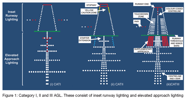
Human perceptions of spaces, architecture, objects and people are dependent on the light that lets us see the world around us. We use light not only to see what we are doing, but also for appearance and for safety. The most obvious applications of lighting systems for safety reasons are traffic signals, street lights and in aviation. Safety is a concern of everyone who flies or contemplates it. No other form of transportation is scrutinised and investigated as closely as commercial aviation. Indeed, in no other use of lighting is standardisation more important than in airport landing lighting, or more specifically, Aerodrome Ground Lighting (AGL). Figure 1 illustrates the typical layout for AGL in the UK. Different categories of lighting are shown where CATI would be used in clear day conditions and CATIII in low visibility conditions.
Essentially these lighting systems are intended to guide pilots during the visual approach to an airport, during landing and also in the take-off phases of their flight. Considering that aviation spans the globe, it is imperative that aircrews worldwide be provided with consistent lighting information that is operating to the required standards.
Researchers at the Queen’s University Belfast are working alongside Cobham Flight Inspection Ltd. to develop a novel intelligent device that will be able to examine landing lighting and determine whether it is operating at the correct brightness and uniformity, as dictated by aviation governing bodies. This article details the need for this research and the progress that has been made to date in the realisation of a prototype monitoring device.
Background
Estimates show the total air traffic doubling in the next 10-15 years. It therefore becomes imperative to maintain the safety of air travel and associated infrastructure by every means possible.
As far as is practicable, the use of airport lighting provides at night and in low visibilities, the same cues that a pilot would see in clear daytime conditions. To do this, the lighting is designed so that, by reference to location and pattern characteristics, a pilot can continuously determine and monitor the position and velocity of the aircraft. Pilots then maneuver their aircraft in response to what they perceive from these visual cues.
Standard airport lighting configurations consist of runway luminaires that are inset into the runway. Approach luminaires, however, extend beyond the runway and are installed at an elevated level above the ground. Standard patterns are shown in Figure 1.
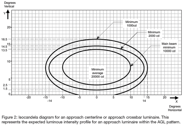
Strict standards exist to ensure luminaires are operating at the correct intensity and alignment. These standards exist in the form of isocandela diagrams. An example of such a diagram is shown in Figure 2 for an approach luminaire.
Presently, most airports can only assess the quality of their lighting installations from flight tests with subjective observers and spot readings using the appropriate light meters. Recently, some airports have moved to using the Mobile Airfield Light Monitoring System which can assess, using a mobile vehicle, the quality of luminaires in the runway, although not the elevated approach luminaires.
Since airport landing lighting is designed to be viewed from the air, it seems reasonable to assume that any device used to assess the quality of the lighting, should also be used from the air.
Hence, the research described in this article concentrates on the development of a system which can monitor the performance of both runway and approach luminaires.
The solution
Today’s improved low cost digital imaging technology makes it possible to develop an intelligent inspection system for airport landing lighting control, that records information with a number of cameras and sensors. The proposed system will use vision sensors capable of recording high-resolution visual information at high speed. The vision data will be stored on hard disk, together with data from various other sensors, to determine the exact location of the recording and to be able to synchronise all data in time and space. The function of the camera is to record what the pilots see during a standard approach and store the information on exchangeable media for off-line performance assessment. In order to assess the performance of the luminaires in terms of their luminous intensity, or the uniformity of the complete pattern, it is necessary to uniquely identify each luminaire in the collected images of the lighting pattern and track them through the complete image sequence. This process is outlined in section 3.1.
A process termed ‘uniformity’ is first used to assess the performance of the complete landing lighting pattern. This assumes that luminaires lying in close proximity to each other and having the same luminous intensity also have the same intensity relationship within the captured images. The luminaires can then be banded according to their expected luminous intensity. Those in the same band are then compared against each other and each is classified into one of four groups: fail, under-perform, pass and over-perform. This process is outlined in section 3.2.
Finally, it is also possible, from the collected image data, to derive the luminous intensity of the imaged luminaires. This is a much more complicated issue than simply assessing the uniformity of the complete pattern. The theory of this process is reviewed in section 3.3.
Unique luminaire identification
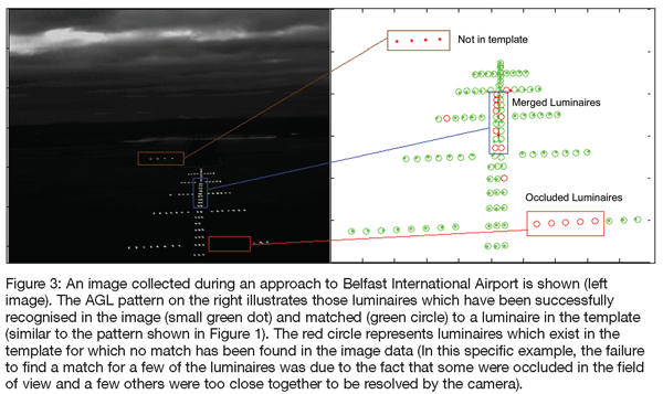
In our research, the collected images are compared to a template of how the lighting pattern is expected to appear to the pilot. By minimising the square of the difference in distance between the features in the template and the features extracted from the image (through a correspondence technique), it is possible to identify which image feature represents which luminaire in the AGL. This correspondence process has proved to be very successful in practice. Figure 3 illustrates the basic process.
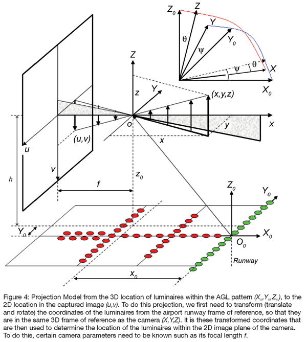
Once the luminaires have been uniquely identified, there is a direct pairing of real world position in the airport lighting coordinate system, and pixel position in the collected image. Provided that the camera used to collect the image is accurately calibrated, it is possible to estimate the position and orientation of the camera at each instant an image was taken. Indeed, being able to estimate position and orientation information from image data is a well researched area in computer vision.
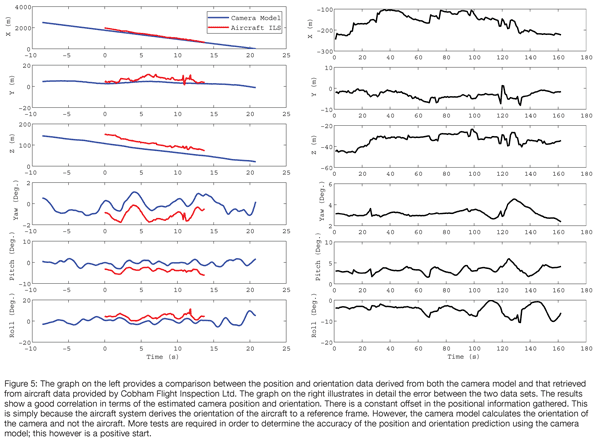
To do this we make use of a simple pinhole camera projection model. Figure 4 illustrates the basic concept of this process. To test the accuracy of the position and orientation estimation, the data derived from our analysis was compared to data collected using Cobham’s Flight Inspection System. Initial results from this comparison are presented in Figure 5.
Uniformity assessment
Uniformity assessment is one type of performance metric for the airport landing lighting. This type of assessment simply assesses the similarity between luminaires which should have the same luminous intensity. Figure 2 showed that the expected luminous intensity of a luminaire can be obtained from the relevant isocandela diagram, if the angular displacement between the luminaire and the measuring device are known. In section 3.1, we described a method by which the position and orientation of the camera, relative to the AGL, can be estimated with a high degree of precision. Using knowledge of the 3D layout of the airport lighting pattern, it is therefore a relatively easy step to compute the angular displacement of the camera, at the instant that each image was taken, from each luminaire in the pattern. Therefore, for each image, the expected luminous intensity of each identified luminaire is known.
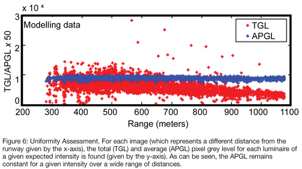
Basic camera imaging science tells us that when we take a 2D image of the 3D world, the image will vary depending on the brightness of the scene. For example, for a normal 8 bit camera each pixel within the image can occupy any value in the range from 0 (black) to 255 (white). As such, when luminaires have a higher intensity, their associated pixel values in the image will also be higher. Another interesting trend is that the average intensity value of all pixels representing a single luminaire in the image remains constant and is independent of distance. This is shown in Figure 6.
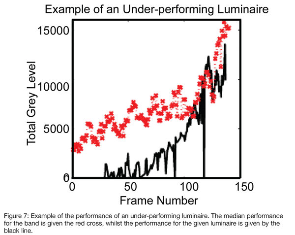
Using this theory, it was possible to group luminaires into bands of similar performance. If a luminaire was constantly underperforming or over performing according to the median performance of the band, then it is reasonable to say that the luminaire is not performing according to the standards. Figure 7 shows the performance of a luminaire that was constantly underperforming. The recommendation would be that this luminaire should be checked, as there is a high probability that its luminous intensity is lower than standards require.
Luminous intensity estimation
By extending the work described in the previous section, it is also possible to relate the average pixel level of a given luminaire to the actual luminous intensity of that luminaire. In order to do that, it is important to know accurately the position and orientation of the camera at the instant the image was taken and the light loss and attenuation in both, from air and the aircraft windscreen. Using this knowledge, a model has been developed which relates grey level information to luminous intensity information. However, this model is currently being tested and validated and so is not presented here.
Conclusions
The main objective of the work at QUB is to develop a system to automatically assess the performance of airport lighting installations. The results from our research to date have indicated that it is possible to assess the performance of both the ground based runway luminaires and the elevated approach luminaires. Further testing is needed to produce a fully validated system, however, when this is achieved, it will revolutionise the maintenance of airport lighting and ultimately enhance the safety of operations at airports worldwide.







Acknowledgements
The authors would like to thank the EPSRC (EP/D05902X/1), The Royal Society and Cobham Flight Inspection Ltd. for financial assistance and research support.
About Dr Karen McMenemy
Karen is a lecturer at Queen’s University Belfast, in the Intelligent Systems and Control Group within the School of Electronics, Electrical Engineering and Computer Science. She has ten years experience working in the fields of computer vision, graphics, and image processing. Dr McMenemy received her PhD in image processing for photometric assessment in 2002. Her PhD research was funded by the Civil Aviation Authority (CAA) and it led to significant advances in the automated measurement of airport lighting. Whilst significant advances have accrued since this original proof of concept, much additional research is required before any form of exploitation can be expected.


